

Introduction: Why the Pinout Matters
Imagine you have an ESP32 DevKit sitting on your desk. You want to connect an LED, read a sensor, control a motor, or connect a colour TFT display.
You open the board’s pinout diagram and find a long list of labels:
GPIO23, GPIO34, ADC, TX, RX, SDA, SCL, MOSI, MISO…
What do they mean? Can you use any pin for anything? Why does one pin work with an LED while another refuses to behave like an output?
Understanding the ESP32 pinout is the first step toward building reliable embedded projects.
In this article, we’ll explore the major pin groups, understand their functions, and learn how to choose suitable GPIOs for our projects.
Any concept that feels unfamiliar or difficult right now will become more intuitive as you progress through this series and start building real projects.
These explanations are here to introduce you to the terminology, not to make you master everything at once. As you experiment, write code, and troubleshoot actual hardware, these concepts will gradually fall into place. It’s Not Hard At All!
Understanding the ESP32 DevKit
For this series, we’re using the classic ESP32 DevKit boards built around the ESP32-WROOM-32 module.
You may encounter boards with 30 pins or 38 pins. Although they can look different, both can expose the same underlying ESP32 capabilities. The exact pins brought out to the headers, their positions, and the board layout can vary.

A useful distinction:
- ESP32: The microcontroller family.
- ESP32-WROOM-32: A module containing the ESP32 chip and supporting circuitry, including its antenna.
- ESP32 DevKit: A development board that makes the module easier to power, program, and connect to external circuits.
The labels printed beside the header pins generally identify their GPIO numbers or special functions.
GPIO: The General-Purpose Input/Output Pins
GPIO stands for General-Purpose Input/Output
These pins allow the ESP32 to interact with external hardware. Depending on the pin’s capabilities and configuration, it can read a digital signal or produce one.
For example:
- Read a push button.
- Turn an LED on or off.
- Read a digital sensor output.
- Send a control signal to another circuit.
A digital input generally reads a logic LOW or HIGH. A digital output can drive a signal LOW or HIGH.
Example: Blinking an LED
#include <Arduino.h>

constexpr int LED_PIN = 23;

void setup() {
    pinMode(LED_PIN, OUTPUT);
}

void loop() {
    digitalWrite(LED_PIN, HIGH);
    delay(500);

    digitalWrite(LED_PIN, LOW);
    delay(500);
}
This example configures GPIO23 as an output and alternates its state every half-second.
Connect an LED with an appropriate series resistor, or use a suitable onboard LED if your particular board provides one. Do not assume every DevKit has an LED connected to the same GPIO.
One important rule: ESP32 GPIOs use 3.3 V logic and are not 5 V tolerant. Do not connect a 5 V signal directly to an ESP32 input. Use suitable level shifting or a properly designed interface when necessary.
Not Every GPIO Is the Same
Although the ESP32 offers many GPIOs, not every pin is suitable for every job.
*Let’s look at the important groups on the classic ESP32.
| GPIO group | What you should know |
|---|---|
| GPIO0–GPIO19 | General-purpose functions are available on many of these pins, subject to individual restrictions. |
| GPIO21–GPIO23 | Commonly used for I²C and SPI-related connections in Arduino examples, but they can also serve other functions. |
| GPIO25–GPIO27 | Useful general-purpose pins; GPIO25 and GPIO26 also provide DAC functionality on the classic ESP32. |
| GPIO32–GPIO33 | General-purpose pins that also support analog input. |
| GPIO34–GPIO39 | Input-only pins. They cannot be used as digital outputs and do not have internal pull-up or pull-down resistors. |
| GPIO6–GPIO11 | Normally connected internally to the module’s SPI flash. Avoid using these as ordinary external GPIOs. |
This is a practical overview, not a complete pinout. Some pins have additional boot, peripheral, or board-specific considerations.
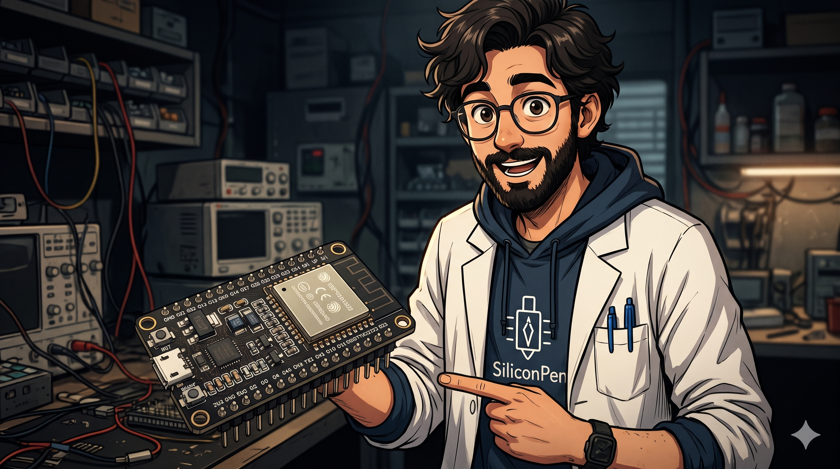
These pins are useful when you only need to read a signal.
For example, GPIO34 can read a digital sensor output or an analog signal within the ADC’s supported input range.
However, you CANNOT use GPIO34 to turn an LED on or generate a PWM output. You also cannot enable its internal pull-up or pull-down resistor.
If you need a pull-up or pull-down, use an external resistor or select another suitable pin.
These GPIOs are typically used by the module’s flash-memory interface. Using them for external hardware can interfere with normal operation.
For our projects, we will leave them alone.
Some pins help determine how the ESP32 starts up. These are called strapping pins.
On the classic ESP32, GPIO0, GPIO2, GPIO5, GPIO12 and GPIO15 have strapping functions. External circuits that force these pins to the wrong levels during reset can prevent normal booting or change startup behaviour.
This does not mean these pins can never be used. It means we must understand their startup requirements before connecting external circuitry.
For beginner projects, prefer a suitable GPIO that does not introduce unnecessary boot complications.
Reading Analog Signals
A microcontroller often needs to measure something that is not simply ON or OFF.
A potentiometer, for example, can produce a range of voltages. A suitable analog sensor may do the same.
An Analog-to-Digital Converter (ADC) converts an analog input voltage into a digital reading that software can process.
On the classic ESP32, ADC-capable GPIOs include pins associated with ADC1 and ADC2.
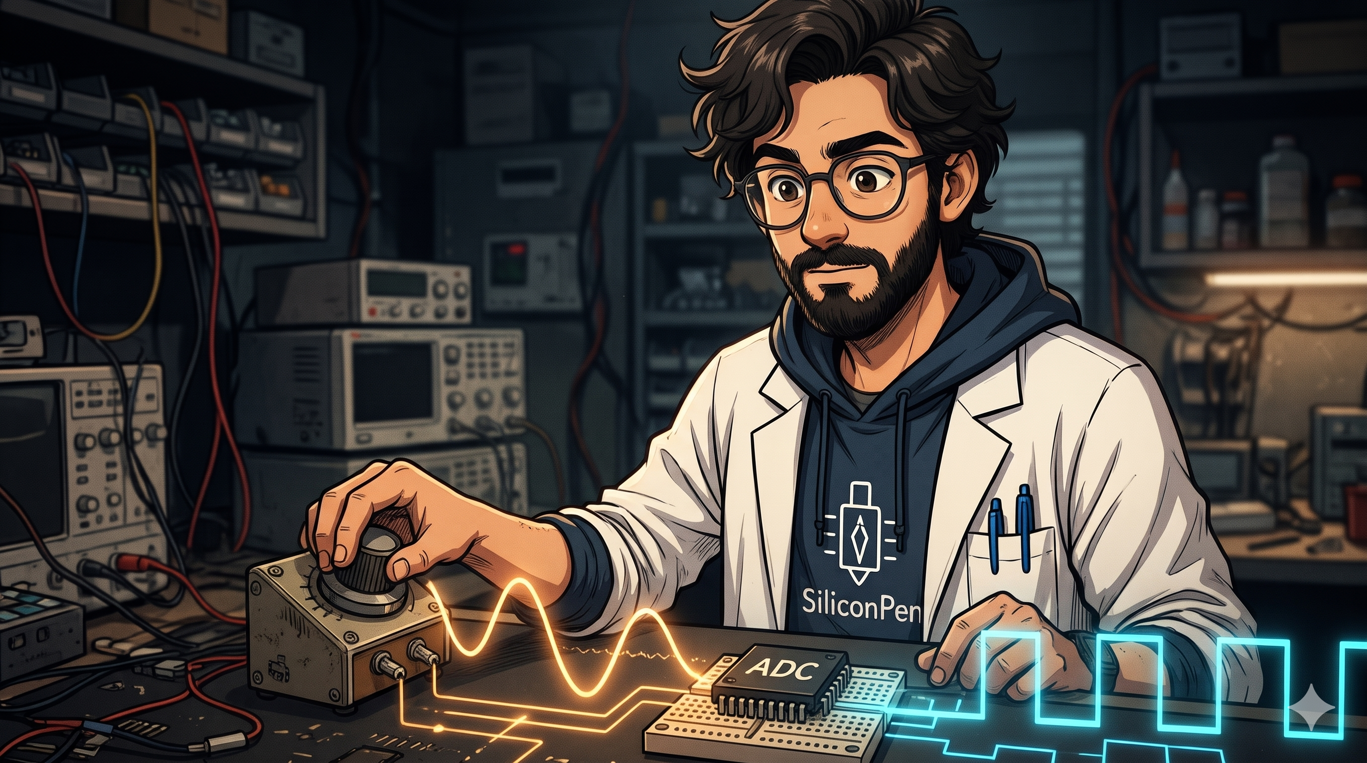
ADC1 and ADC2: An important distinction
On the classic ESP32, ADC2 has restrictions when Wi-Fi is active. Depending on the framework and configuration, ADC2 readings may conflict with Wi-Fi operation.
If your project needs both Wi-Fi and analog measurements, prefer an appropriate ADC1 pin where possible.
Common ADC1 pins on the classic ESP32 include GPIO32–GPIO39. Remember that GPIO34–GPIO39 are input-only, which makes them perfectly suitable for many analog measurements.
Example: Reading an analog input
#include <Arduino.h>

constexpr int SENSOR_PIN = 34;

void setup() {
    Serial.begin(115200);
}

void loop() {
    int sensorValue = analogRead(SENSOR_PIN);

    Serial.print("ADC reading: ");
    Serial.println(sensorValue);

    delay(500);
}
Connect a suitable analog signal to GPIO34 and open the Serial Monitor at 115200 baud.
The serial monitor works the same for Arduino IDE and PlatformIO, but needs to be configured differently which will be taught later. For conceptual knowledge you may refer the link attached to Serial Monitor.
The code prints the ADC reading repeatedly. The exact conversion scale, usable input range, and measurement accuracy depend on the ESP32 configuration and hardware. Do not assume the raw reading is automatically a calibrated voltage.
The input voltage must remain within the ESP32's permitted range. Never connect a 5 V analog signal directly to an ESP32 GPIO.
PWM: Controlling More Than Just ON and OFF
Suppose you want to adjust an LED’s brightness or control the speed of a suitable DC motor through a driver.
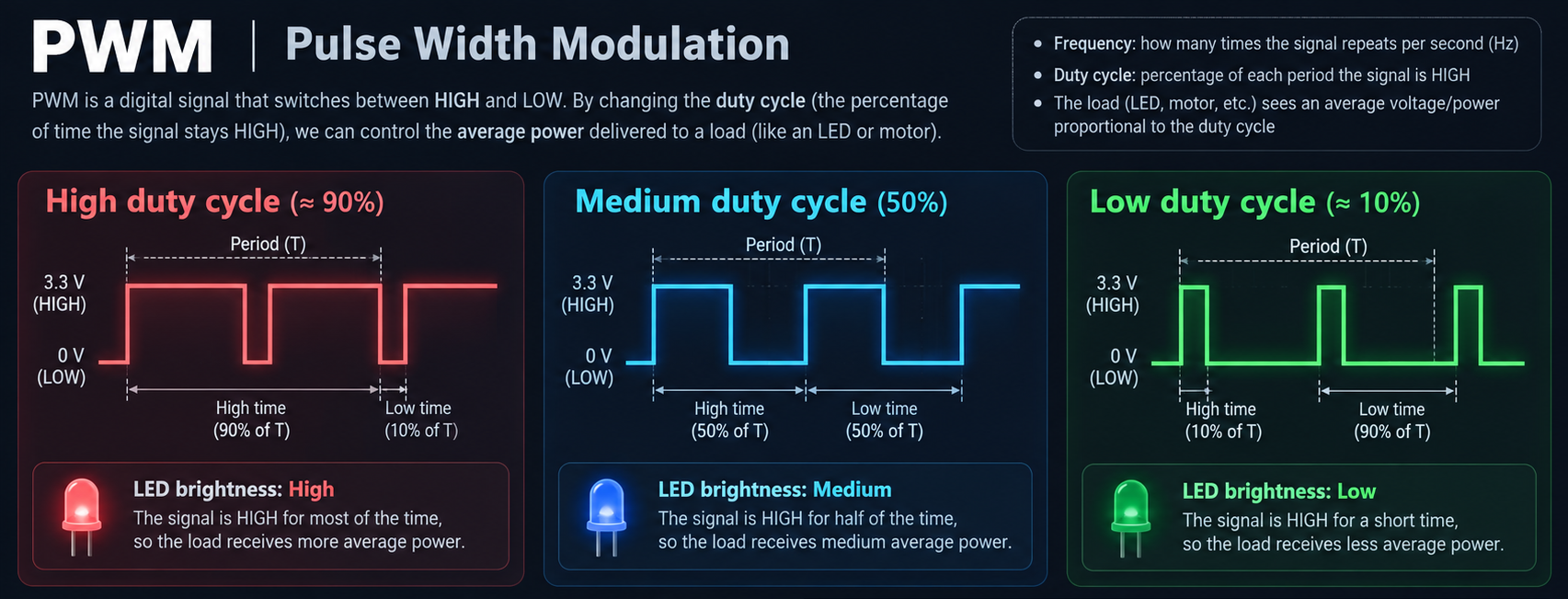
A simple digital output provides HIGH or LOW. Pulse Width Modulation (PWM) gives us a repeating signal whose duty cycle can be adjusted.
The duty cycle is the fraction of each period during which the signal is HIGH.
For example:
- 0% duty cycle: the signal is never HIGH.
- 50% duty cycle: the signal is HIGH for half of each period.
- 100% duty cycle: the signal is continuously HIGH.
For an LED, changing the duty cycle changes its apparent brightness.
The classic ESP32 provides hardware PWM through its LED Control (LEDC) peripheral. Many GPIOs can be assigned to PWM output, provided the pin is otherwise suitable and the peripheral is configured correctly.
PWM is useful for LED dimming, servo-control signals, and motor-driver inputs. These applications do not all use the same frequency or timing requirements.
Example: LED brightness with PWM
This example targets the Arduino-ESP32 core 3.x API.
#include <Arduino.h>

constexpr int LED_PIN = 23;
constexpr int PWM_FREQ = 5000;
constexpr int PWM_RESOLUTION = 8;

void setup() {
    ledcAttach(LED_PIN, PWM_FREQ, PWM_RESOLUTION);
}

void loop() {
    for (int duty = 0; duty <= 255; duty++) {
        ledcWrite(LED_PIN, duty);
        delay(10);
    }

    for (int duty = 255; duty >= 0; duty--) {
        ledcWrite(LED_PIN, duty);
        delay(10);
    }
}
With 8-bit resolution, the duty value ranges from 0 to 255. The code gradually increases and decreases the brightness.
If you are using an older Arduino-ESP32 core, the LEDC API may differ. Always check the version used by your PlatformIO project.
For motors, do not connect the motor directly to a GPIO. Use a suitable motor driver or switching circuit, with an appropriate power supply and common ground where required.
Communication Pins: UART, SPI and I²C
The ESP32 becomes much more useful when it can exchange information with other devices.
Three communication interfaces you’ll encounter frequently are UART, SPI, and I²C.
UART: Serial communication
UART is commonly used for serial communication with computers, GPS modules, and other devices.
The familiar signals are:
- TX: Transmit data.
- RX: Receive data.
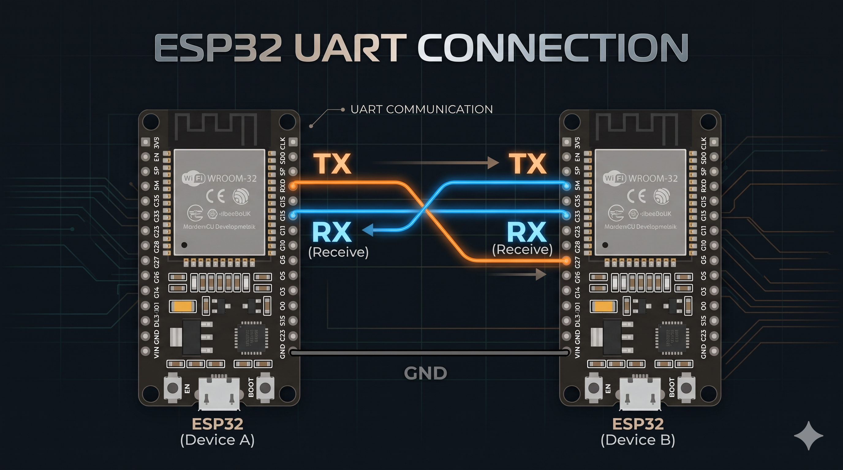
The classic ESP32 has multiple UART controllers, and their signals can generally be routed to suitable GPIOs. GPIO1 and GPIO3 are commonly used for UART0, including USB-to-serial programming and debugging on many DevKit boards.
Be careful when using these pins for other devices, because they may also carry programming or debugging traffic.
In our earlier LED example, we did not need serial communication. But when debugging sensors or more complicated projects, the Serial Monitor becomes an essential tool.
I²C: Two wires for multiple devices
I²C is a synchronous communication bus that commonly uses two signal lines:
- SDA: Serial Data.
- SCL: Serial Clock.
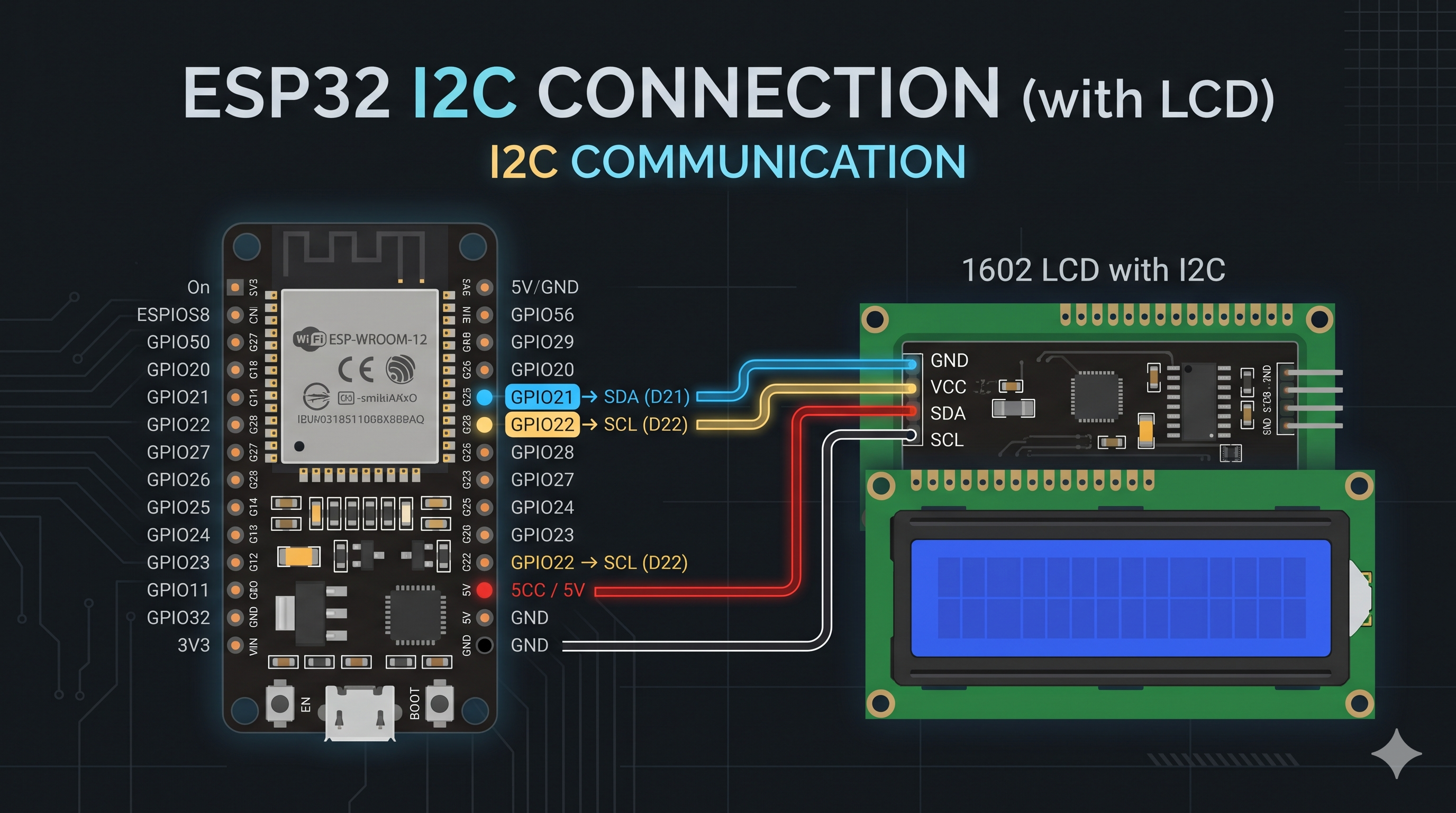
Multiple compatible devices can share the same bus, provided their addresses and electrical requirements are handled correctly.
On many classic ESP32 Arduino setups, GPIO21 is used for SDA and GPIO22 for SCL by default. These are conventions, not fixed hardware requirements: the pins can be configured in software when suitable.
I²C is especially useful for sensor modules, RTCs, small displays, and devices such as PWM controllers.
For example, an external PWM controller can communicate with the ESP32 over I²C while providing additional control outputs for a robotics project.
Remember that I²C lines usually require pull-up resistors. Many breakout boards already include them, but not all do. Also check the voltage used by the bus and any module pull-ups.
SPI: Faster communication with displays and peripherals
SPI is another synchronous communication interface. It is commonly used by colour TFT displays, memory devices, and other peripherals.
Typical signals include:
- SCLK: Serial clock.
- MOSI: Controller-to-device data.
- MISO: Device-to-controller data.
- CS: Chip select for a particular device.
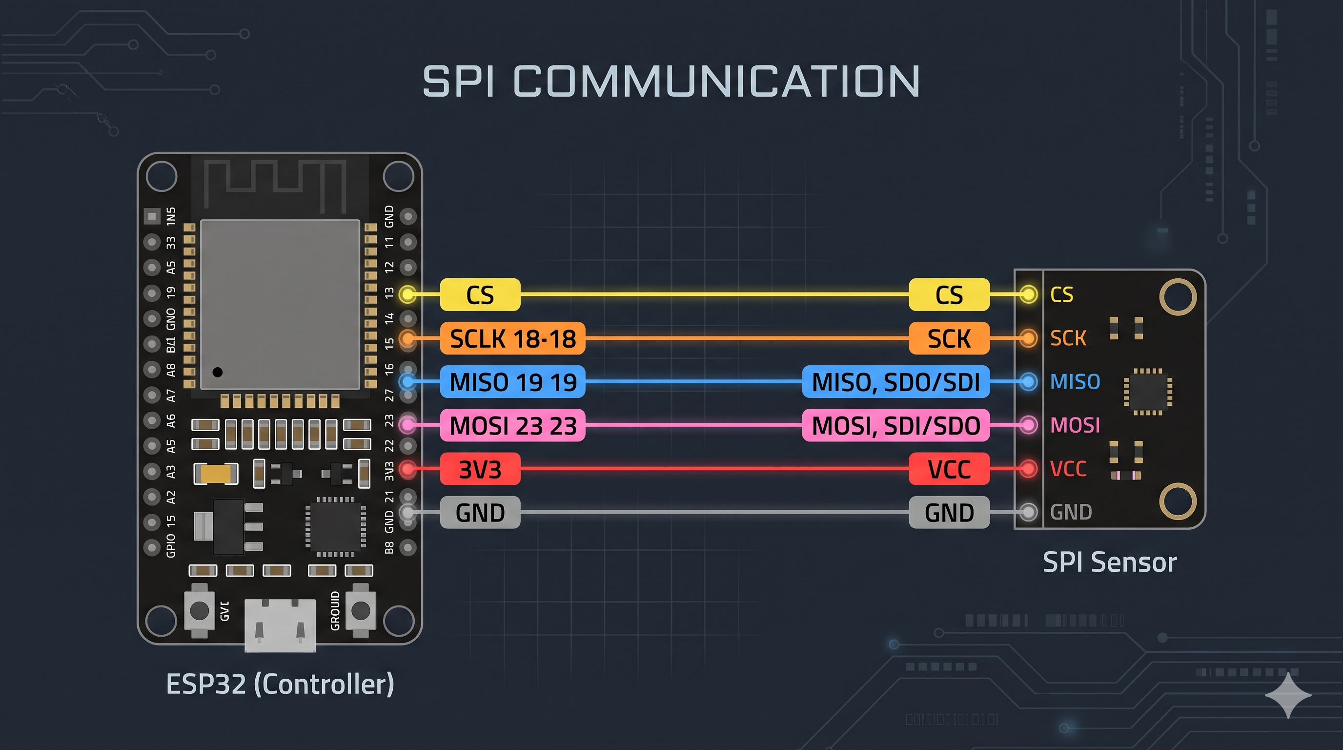
Not every SPI device needs every signal. For example, a display may not use MISO.
On the classic ESP32, common VSPI assignments are GPIO18 for SCLK, GPIO19 for MISO, GPIO23 for MOSI, and GPIO5 for CS. These are common defaults, not mandatory pin assignments.
SPI can be a good choice when transferring data quickly, such as drawing graphics on a colour TFT display.
When connecting a display, always check its controller, interface, pin requirements, and logic-voltage compatibility. Different displays can use different pin labels and configurations.
Which Pins Should You Choose?
You do not need to memorize the entire pinout before building something.
Instead, start with the function you need and select a suitable GPIO.
| Project requirement | What to look for |
|---|---|
| LED or digital output | A suitable output-capable GPIO |
| Push button | An input-capable GPIO with a suitable pull-up or pull-down arrangement |
| Analog sensor | An ADC-capable pin; prefer ADC1 when using classic ESP32 Wi-Fi |
| PWM output | A suitable GPIO supported by the LEDC peripheral |
| I²C sensor | Suitable SDA and SCL pins, configured consistently in software |
| SPI TFT display | Suitable SCLK, MOSI, and chip-select pins, plus any additional display control signals |
| Serial debugging | The board’s USB-to-serial connection and its configured UART pins |
Before connecting anything, check four things:
- Is the GPIO physically available on your exact DevKit?
- Does it support the function you need?
- Will the external circuit operate safely at 3.3 V logic?
- Could the connection interfere with booting, flash memory, USB serial, or another peripheral?
This small checklist can save a surprising amount of debugging time.
A Practical Pinout Workflow
Whenever you start a new project, follow this workflow:
Step 1 — Identify the component.
Find its datasheet or reliable module documentation. Determine the required signals and voltage levels.
Step 2 — Identify the ESP32 board.
Check whether you have a 30-pin or 38-pin DevKit and locate its matching pinout diagram.
Step 3 — Assign GPIOs.
Choose pins that support the required functions and avoid unnecessary boot or peripheral conflicts.
Step 4 — Check the wiring.
Confirm power, ground, signal connections, and any required pull-up resistors, voltage dividers, or drivers.
Step 5 — Test one feature at a time.
Start with a simple program. Verify the connection before adding the next part of the project.
This approach is especially useful when a project contains multiple peripherals, because it lets you isolate wiring and configuration problems instead of debugging everything at once.
Conclusion
The ESP32 pinout becomes much easier to understand when you stop treating it as a list of numbers and start seeing it as a collection of hardware capabilities.
GPIO lets us interact with the outside world. ADC lets us measure analog signals. PWM gives us control over repeating signals. UART, I²C, and SPI allow the ESP32 to communicate with other devices.
Once you understand these functions and the limitations of individual pins, choosing GPIOs becomes a design decision rather than guesswork.
In the next article, we’ll set up Visual Studio Code and PlatformIO so we can write, build, upload, and organize ESP32 projects properly.
We’ll use that environment throughout this series, including when we start building games on a colour TFT display.
References
- Espressif Systems — ESP32 documentation: https://docs.espressif.com/projects/esp-idf/en/stable/esp32/
- Espressif Systems — ESP32-WROOM-32 datasheet: https://www.espressif.com/sites/default/files/documentation/esp32-wroom-32_datasheet_en.pdf
- Espressif Arduino-ESP32 documentation: https://docs.espressif.com/projects/arduino-esp32/en/latest/
- PlatformIO documentation: https://docs.platformio.org/
Comments
Share your thoughts, questions, or corrections below. Be kind and keep it on-topic ✨